Power & wiring
AC 100–250V · 50/60Hz · Live and neutral required
L8-HF / L8-HFU · LCD SMART FAN SWITCH
Control a compatible AC fan from the LCD panel or the app for your selected version. Save three custom speed presets and switch the light independently.
Connectivity options · EU / US · White / Black · Neutral required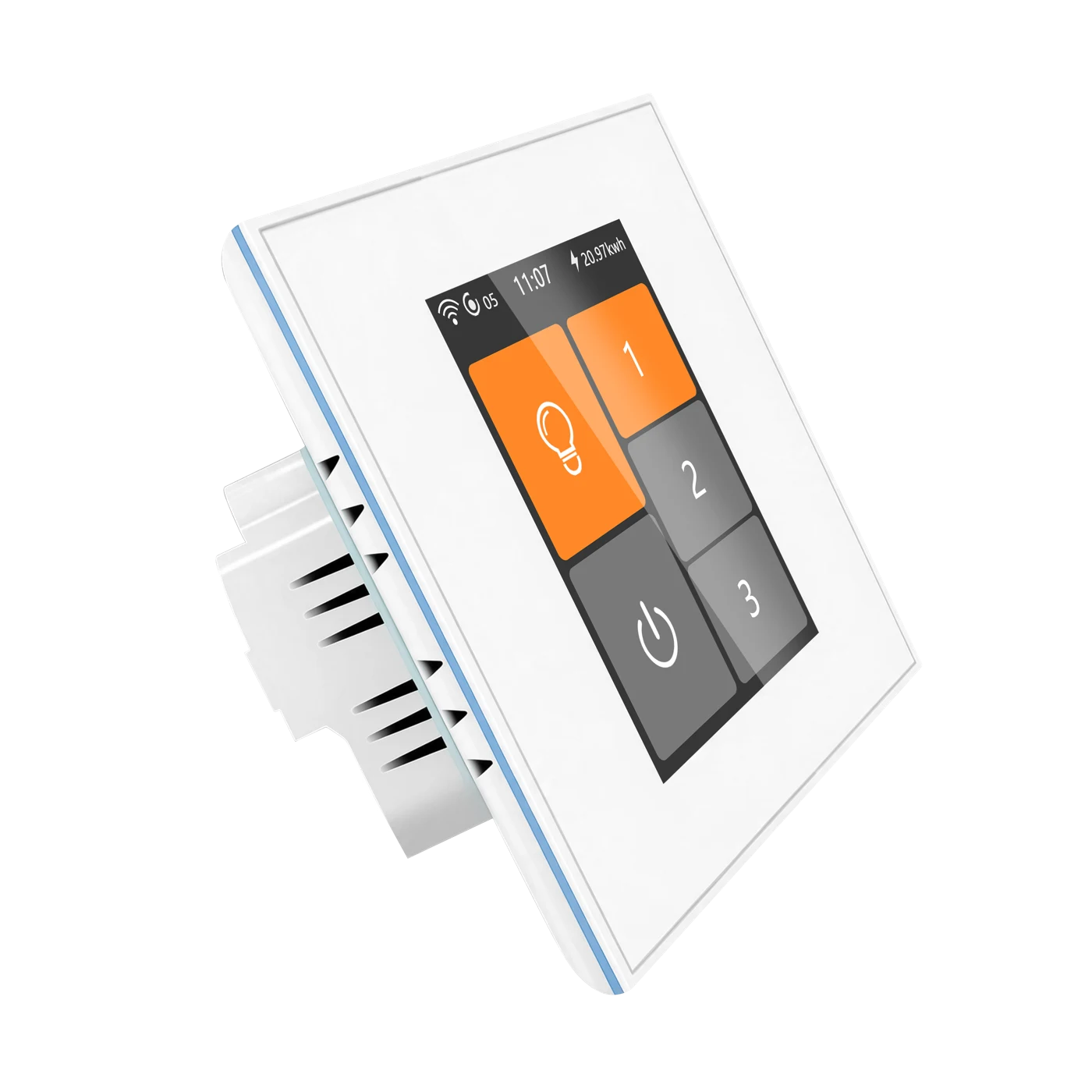
EVERYDAY FAN CONTROL
BEFORE YOU CHOOSE
Have a qualified electrician check the actual motor, supply, load and wiring. Fan and light outputs serve different purposes and must not be swapped.
AC 100–250V · 50/60Hz · Live and neutral required
One compatible single-phase AC fan ≤200 W. No parallel motors.
Independent on/off ≤200 W; no dimming.
For compatible traditional AC motors, including PSC. No DC variable-speed fans or built-in remote/smart speed controllers.
Recommended motor load >15 W and starting setting >10%. Verify reliable starting; do not test speed control without a motor connected.
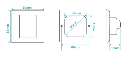
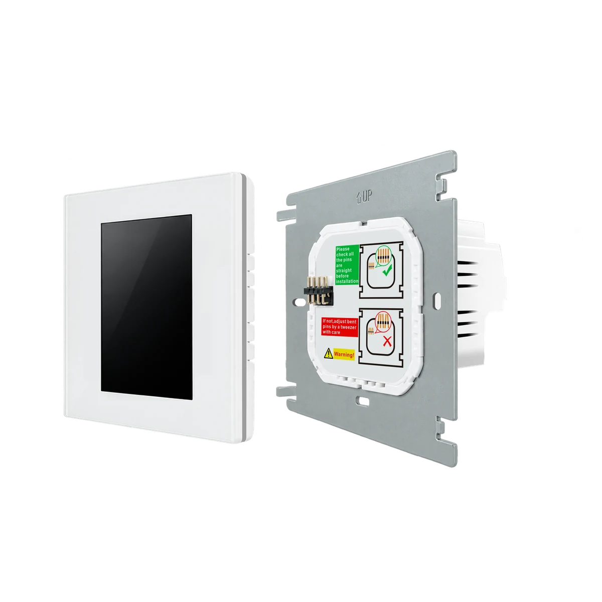
Depth >38 mm plus wiring space; EU fixing 60 mm / US 83 mm. Follow the selected drawing.
LCD FAN CONTROL
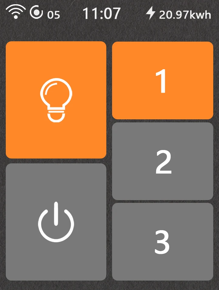
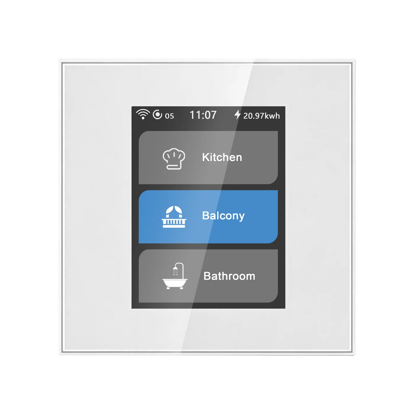
Use fan-only or fan-and-light control to suit your installation, and customise three speed shortcuts. Images below show real device interfaces.
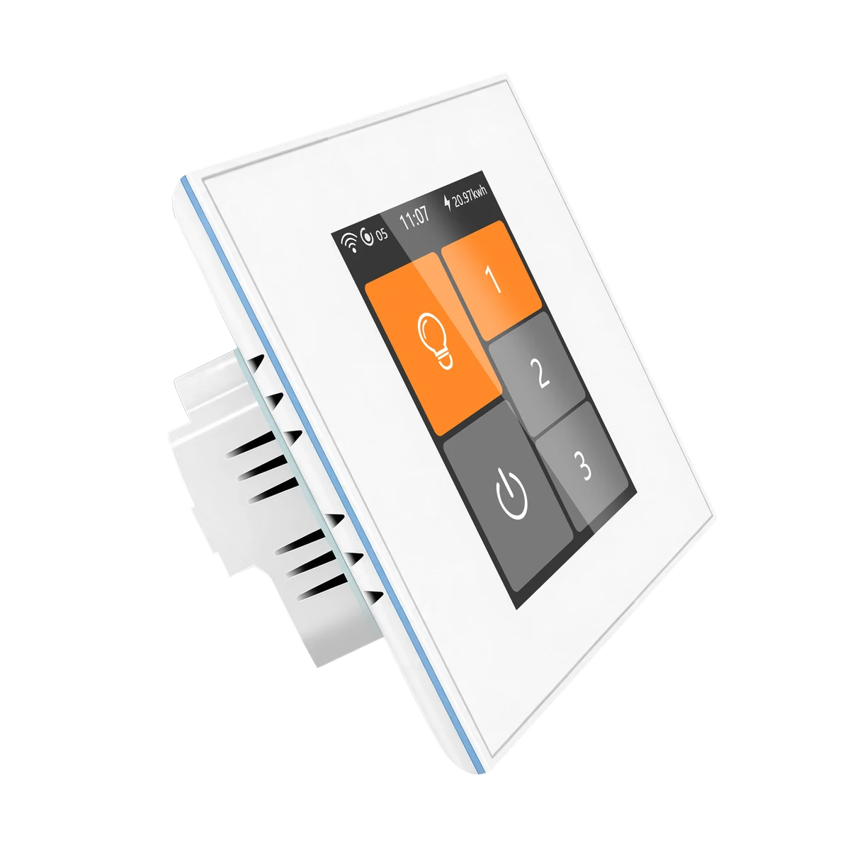
Use the LCD panel to control a compatible AC fan and recall a saved speed.
Select a tab to explore the interface. Actual setup takes place on the device or app; speed settings are not measured motor RPM.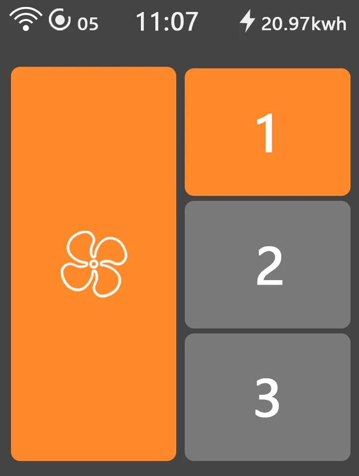
PERSONALISE YOUR DISPLAY
Choose a theme, adjust screen brightness in device settings and set the display orientation to match the installation. This model does not support proximity wake.
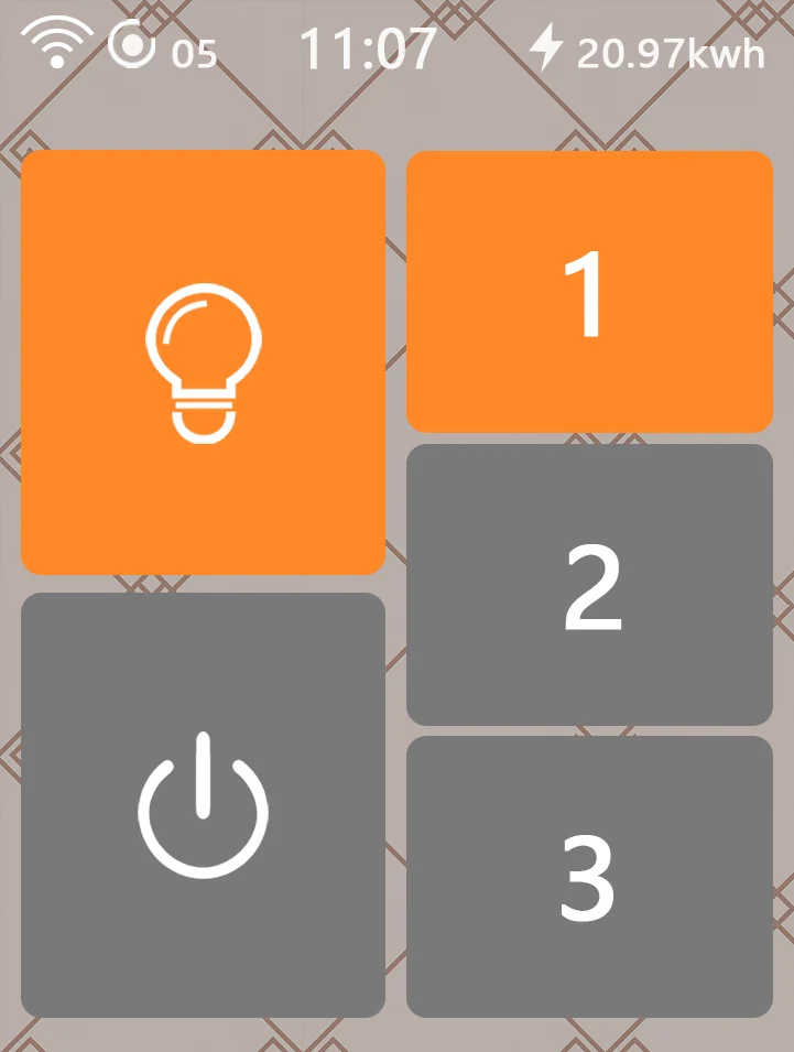
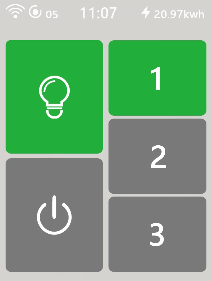
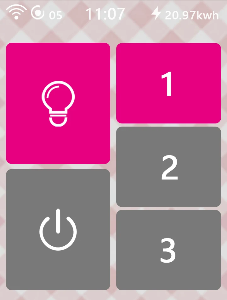
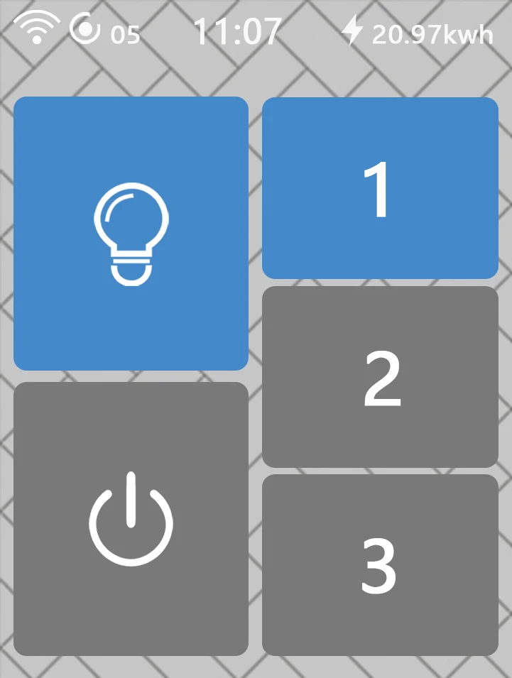
L8 · Themes
Choose among five supplied screen themes. Theme colours change the interface, not the connected lamp colour or fan performance.
L8 · EDGE LIGHTING
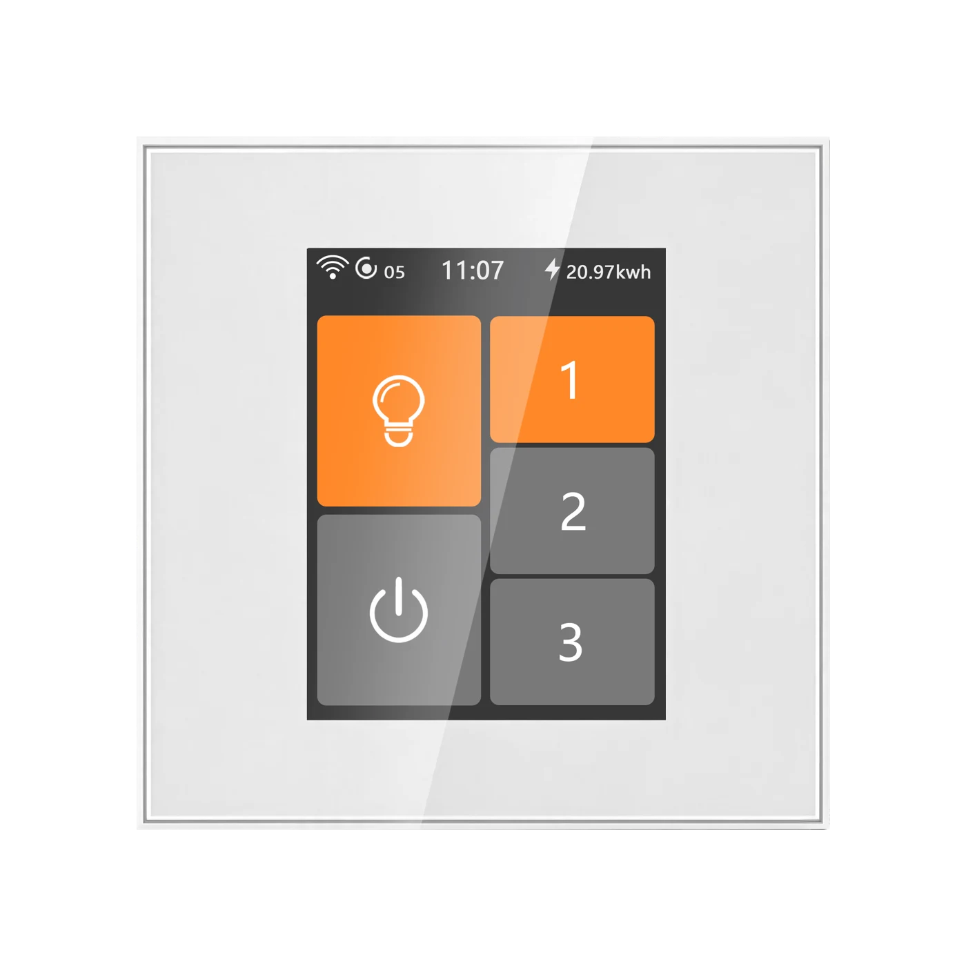
Let the panel edge breathe and change colour while idle, or choose a colour of your own. The decorative edge light is separate from the controlled lights or appliance.
EXPLORE THE GLOW
Let the edge light fade gently in and out as its colour changes. Automatic mode takes care of the colours for you.
Set the edge light and its time settings on the device. These controls preview the effect on this page; they do not configure a switch.
YOUR SPEED PRESETS
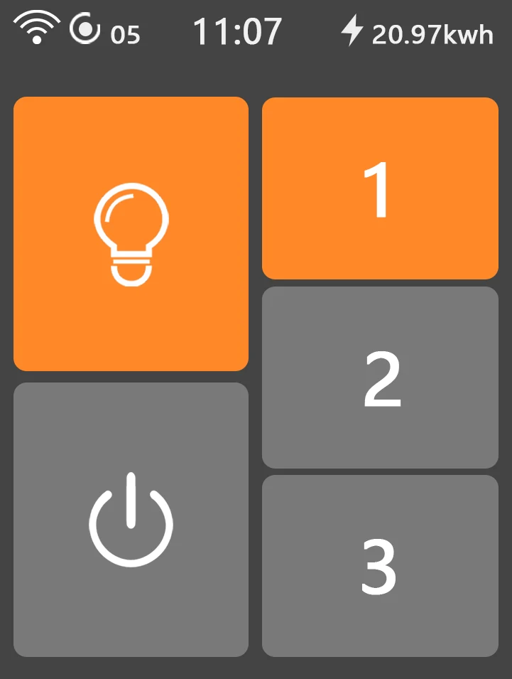
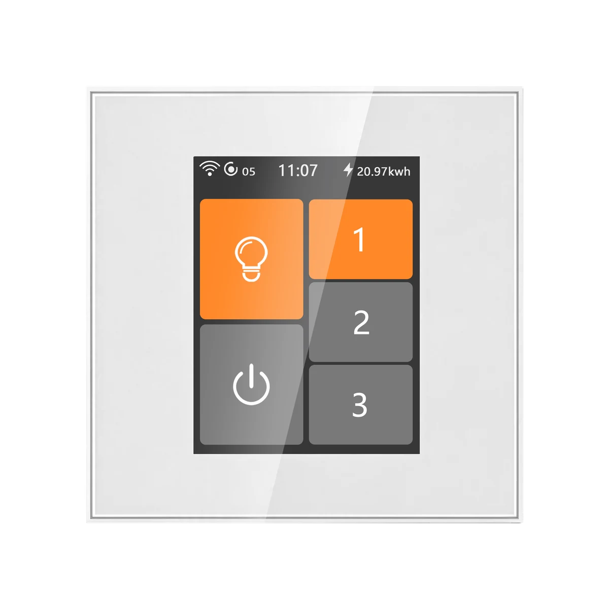
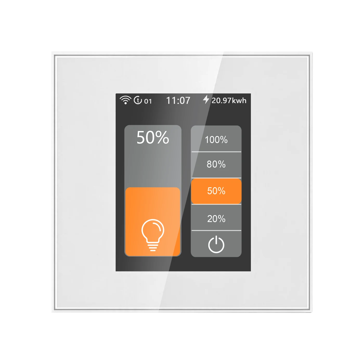
Set each preset within the 1%–100% control range. The examples show selected shortcut buttons, not fixed low/medium/high RPM. Actual speed and reliable starting depend on the connected motor.
Adjust each shortcut in the device's preset-speed settings. Fan control uses TRIAC regulation; some compatible motors may produce a slight hum at lower settings.
SMART LIVING
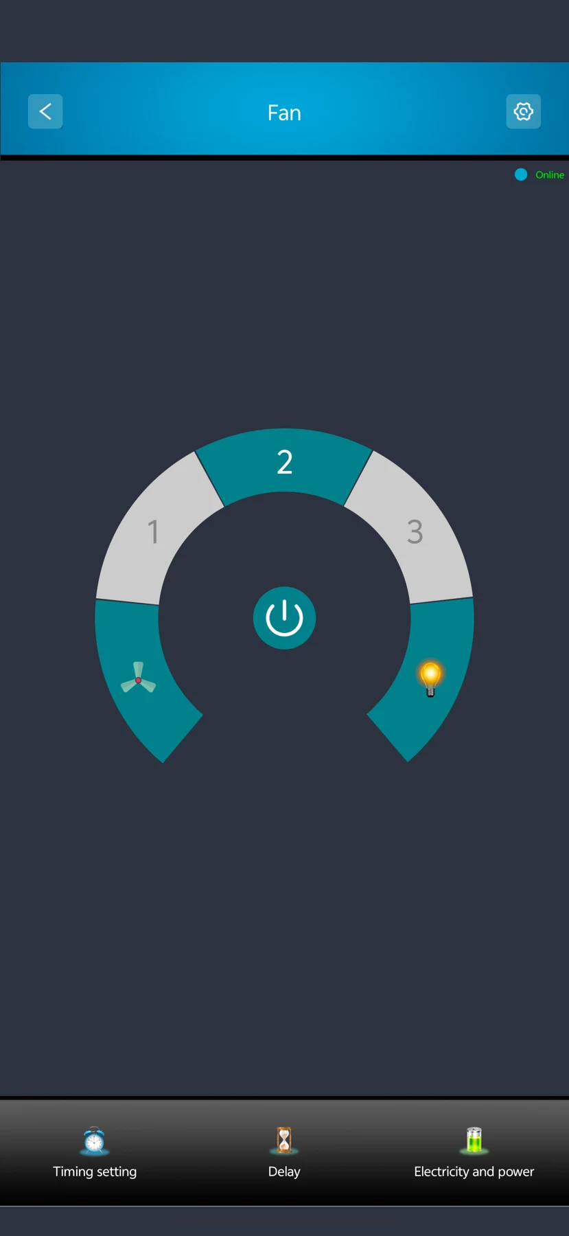
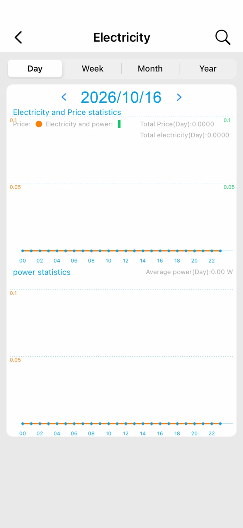
Use Smart Living for fan control, schedules and energy information. Connected features require setup, 2.4 GHz Wi-Fi and available network services. Screenshot figures illustrate the interface.
WI-FI MESH
Mix compatible L8 switches in one network: 7-in-1, 4-in-1, dimmer, fan and water heater controls. Switches connect through neighbouring nodes, so each switch does not need a direct Wi-Fi connection to the router.
 First configured switch7-in-1 switch · Master example
 Dimmer switchConnects through MeshFan switchConnects through Mesh
 Water heater switchConnects through Mesh
Configure the first switch where the router signal is good. The system automatically sets this first configured switch as the master.
Complete setup for the other compatible switches. Keep adjacent Mesh switch nodes no more than 8 metres apart.
The switches automatically form their Mesh network. Any compatible switch can serve as the master when configured first; a separate gateway or host is not required.
L8 switches form a network within the L8 series; it does not extend household Wi-Fi for phones or computers. Remote app and cloud features still require the router, internet access and available services.
L8-HF · LANBON edition
Send commands and receive device state through your own MQTT broker.
MQTT developer guide →Read device capabilities, send commands and retrieve state through the LANBON local API.
Use the local API →PRODUCT VIEWS
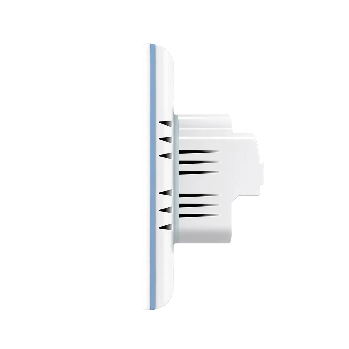
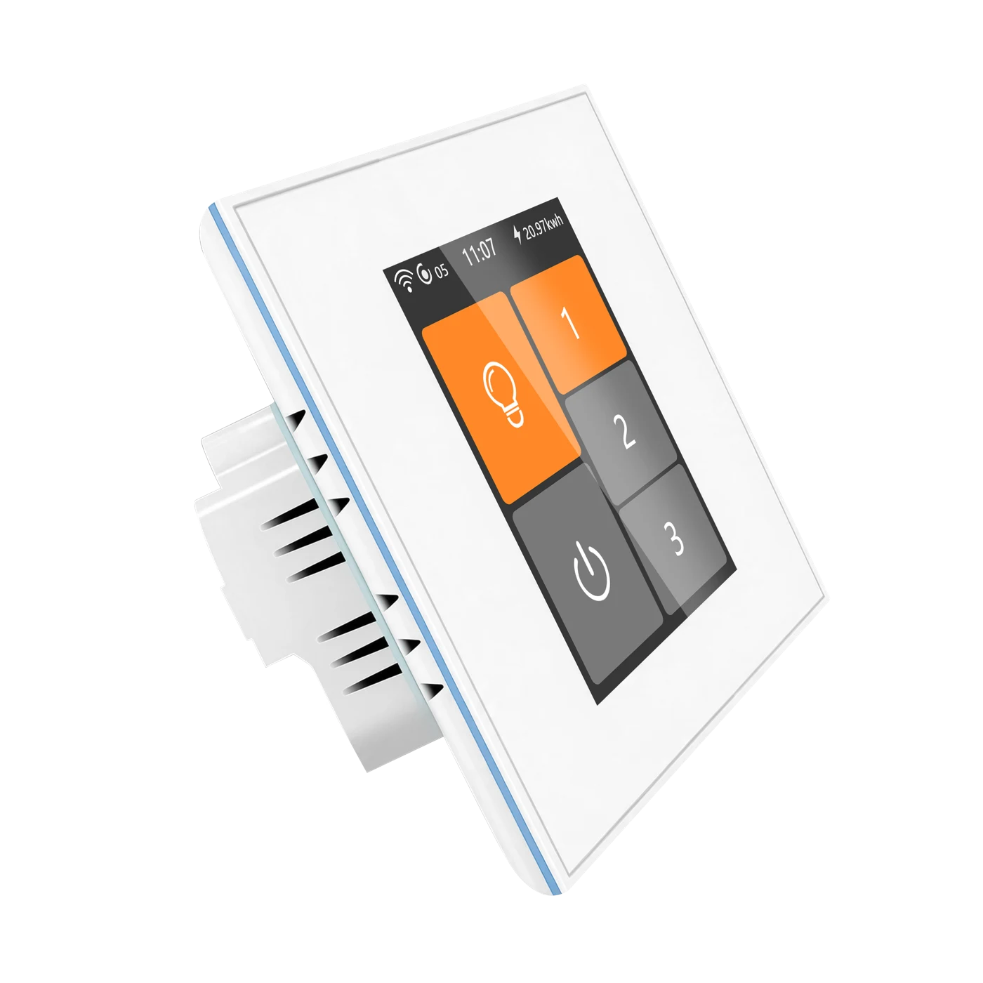
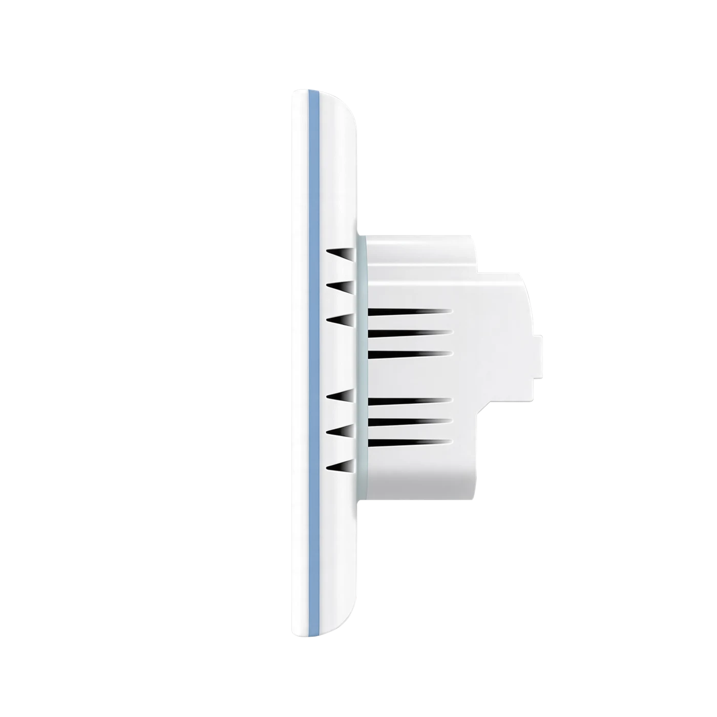
L8-HF · 86 × 86 mm · White
MODEL & SPECIFICATIONS
Dimensions, fixing points and documents follow your selected EU or US panel.
EU: 86 × 86 mm square or ≥60 mm round box; 60 mm fixing centres.
Verify the actual terminals and model-specific wiring instructions with a qualified electrician before connection.
FAN & LIGHT COMPATIBILITY
For a compatible traditional single-phase AC ceiling, exhaust or wall fan within 200 W. Check that the specific motor supports the switch's TRIAC speed-control method and starts reliably at the chosen setting.
The relay light output supports compatible LED, incandescent or CFL lighting within 200 W. It switches power only; it does not dim or control motor speed.
DC variable-speed fans, fans with built-in remote receivers or smart speed controllers, parallel fan motors, over-rated loads, or non-lighting high-power appliances on the light output. Do not swap fan and light outputs.
INSTALLATION
WATCH IT WORK
The supplied fan-control illustration; not a measured motor-speed comparison.
Fan control in the supplied Smart Living demonstration.
DOCUMENTS & SUPPORT
Preview, read or download dimensions, wall-box requirements and package contents. Contact support for current model-specific operating and wiring instructions, certification scope and regional service terms.